About Course
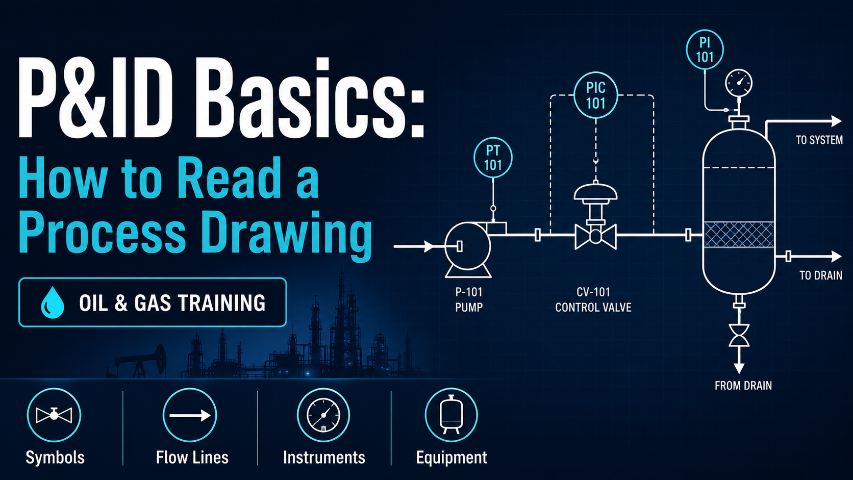
P&ID Basics: How to Read a Process Drawing introduces the fundamental skills needed to understand Piping and Instrumentation Diagrams used in oil, gas and process facilities.
The course explains how major equipment, process piping, valves, instruments and control loops are represented on a P&ID. Learners will understand common symbols, line types, equipment and instrument tags, flow direction, valve functions, and the relationship between field equipment and process control.
By the end of the course, learners should be able to approach a basic P&ID systematically, follow a process flow path and identify the main equipment, piping, isolation points and instrumentation shown on the drawing.
Student Ratings & Reviews

No Review Yet